

The basket is empty.


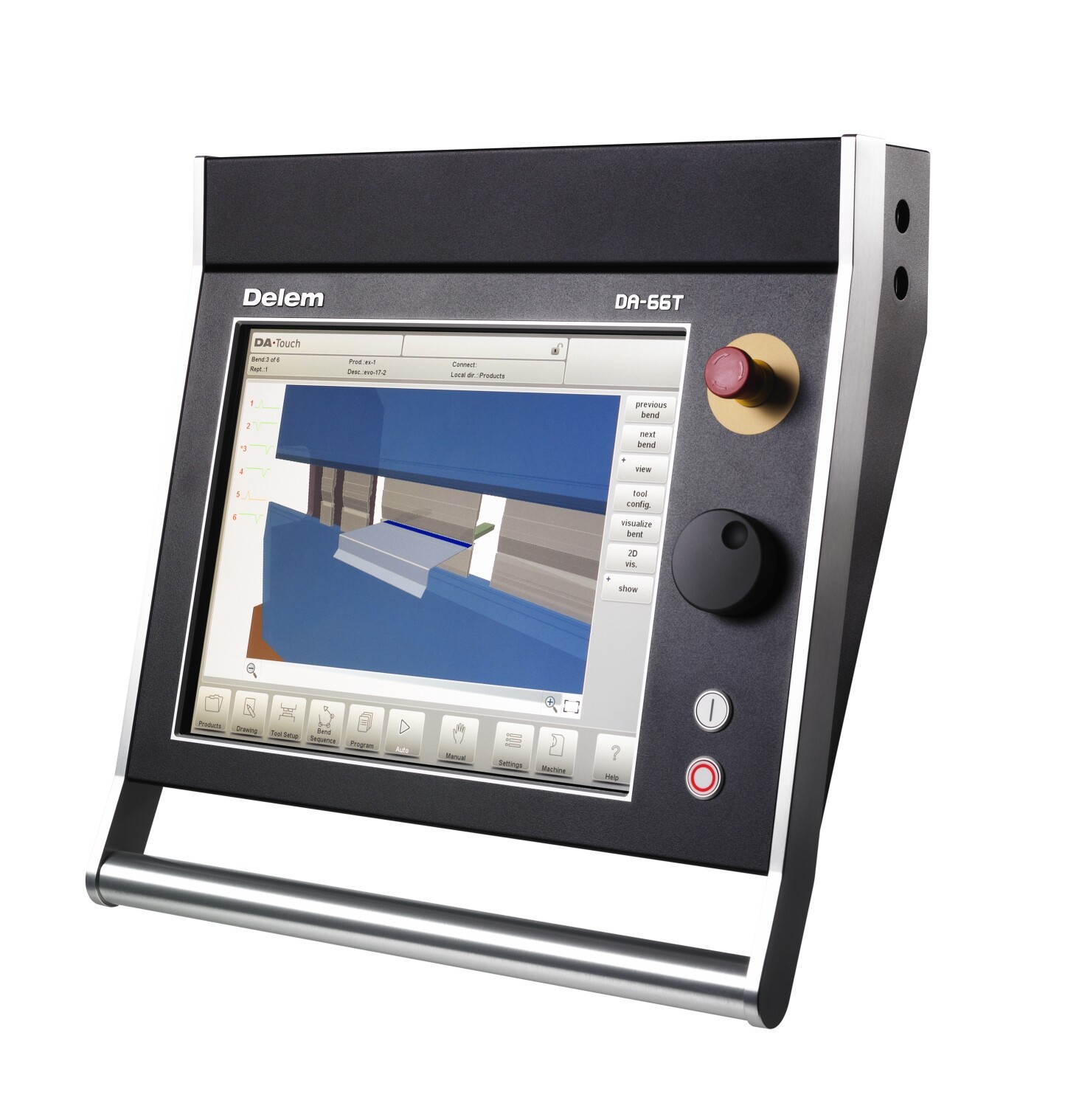
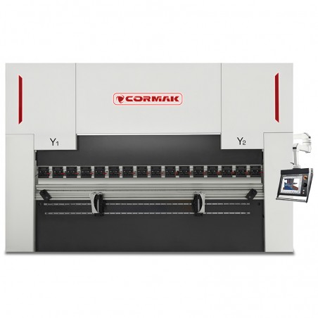
CORMAK press brakes are advanced machines designed for precise sheet metal bending with properly matched punches and dies. Our range includes models equipped with the DELEM DA-53TX controller as standard, with optional controllers DELEM DA-53T, DA-58T, DA-66T, DA-69T and CYBELEC 12, offering a wide range of functions for the most demanding bending tasks.

| Max. sheet thickness (S235) | up to 3.0mm |
| Nominal pressure | 400kN |
| Maximum bending length | 1600mm |
| Throat depth | 200mm |
| Maximum ram stroke | 100mm |
| Maximum opening height | 300mm |
| Distance between side frames | 1200mm |
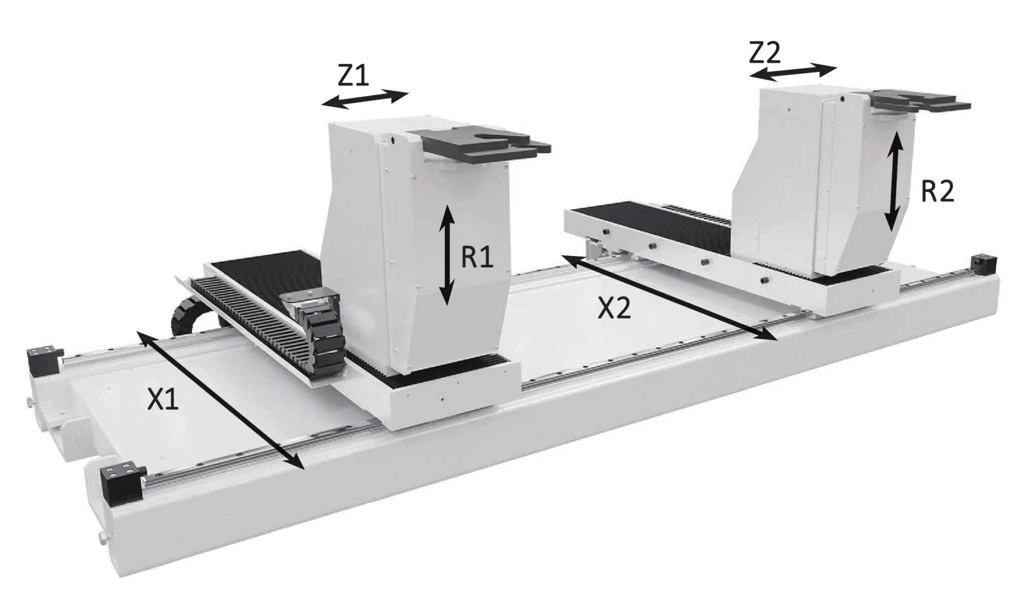
| Back gauge travel | 600mm |
| Motor power | 4.0kW |
| Length | 1800mm |
| Width | 1200mm |
| Height | 1850mm |
| Weight | 2600kg |


Although the step-bending process may seem complex, CORMAK machines and software are advanced enough to automate most of the operator’s work.

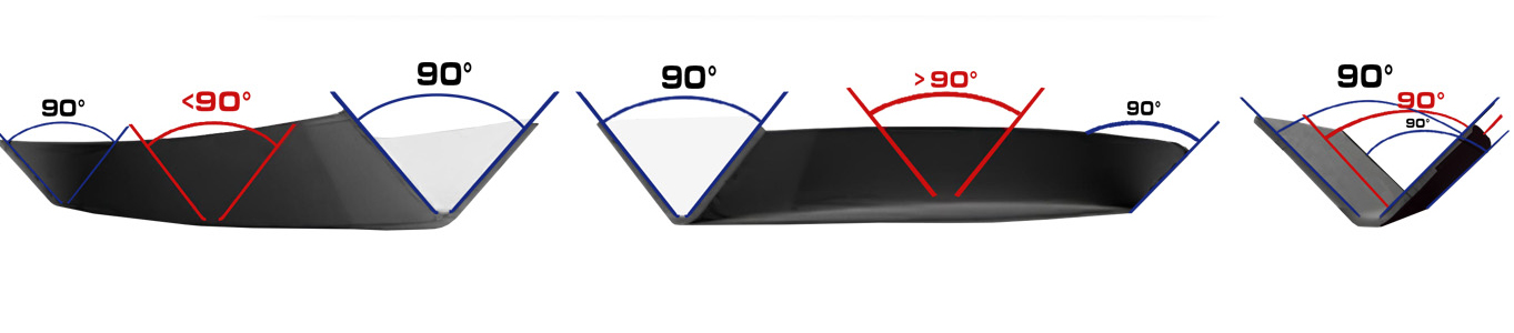
Ensures a consistent bending angle along the full bending length.

Ensures uniform bending angle over the entire working length – (option*)


Optional controllers also available: DELEM DA-53T+2D, DA-66T, DA-69T or CYBELEC 12


The machine combines advanced technology with user-friendly operation, making it ideal for both precise manual work and efficient serial production. High-quality components and advanced safety systems ensure reliability and operator protection.
Equipped as standard with a top-class laser safety system protecting the operator and more than doubling bending productivity.

We never compromise on safety! Top-class hydraulic connections and safety valves designed and manufactured with CE compliance.


Supplied as standard, ensuring stable machine parameters even during long, continuous operation.
For the final result, it is essential to choose the right tooling – die and punch.
CORMAK press brakes continuously monitor bending parameters and can correct deviations during operation to ensure optimum results.


It is possible to arrange professional training and machine commissioning carried out by a Cormak technician — this service is priced individually.
Contact our advisor to get more information.
*The price quoted is for the machine itself, excluding optional/additional equipment, installation, transport and training — please contact our consultant for more details.
Manufacturer: Cormak

CORMAK JERZY ZALEWSKI
Brzeska 120, 08-110 Siedlce, Poland
phone: +48 501 944 934
export@cormak.pl
phone: +48 609 939 400
export@cormak.pl
phone: +48 609 939 051
export@cormak.pl
phone: +48 609 939 741
export@cormak.pl


Hydraulic Press Brake CORMAK CNC SERVO ELITE 200×4000 DA-53TX,
CORMAK press brakes are advanced machines designed for precise sheet metal bending using properly selected punches and dies. Our offer includes models equipped with the DELEM DA-53TX controller as standard and optionally DELEM DA-53T, DA-58T, DA-66T, DA-69T and CYBELEC 12 controllers, which provide ...More

Hydraulic Press Brake CORMAK CNC SERVO ELITE 300×5000 DA-53TX
CORMAK press brakes are advanced machines enabling precise sheet-metal bending through perfectly matched punches and dies. The range includes models equipped with the DELEM DA-53TX controller as standard, with optional controllers DELEM DA-53T, DA-58T, DA-66T, DA-69T and CYBELEC 12, providing a ...More

Hydraulic Press Brake CORMAK CNC SERVO ELITE 250×5000 DA-53TX
CORMAK press brakes are advanced machines designed for precise sheet metal bending using properly selected punches and dies. Our range includes models equipped with DELEM DA-53TX controllers as standard and optionally DELEM DA53T, DA-58T, DA-66T, DA69T and CYBELEC 12, which provide a wide range of ...More

Hydraulic Press Brake CORMAK CNC SERVO ELITE 80×2500 DA-53TX
CORMAK press brakes are advanced machines enabling precise sheet metal bending using properly selected punches and dies. Our offer includes models equipped as standard with the DELEM DA-53TX controller and optionally with DELEM DA53T, DA-58T, DA-66T, DA69T and CYBELEC 12 controllers, which provide ...More

Hydraulic Press Brake CORMAK CNC SERVO ELITE 125×4000 DA-53TX
CORMAK press brakes are advanced machines enabling precise sheet bending thanks to properly selected punches and dies. Our range includes models equipped with the standard DELEM DA-53TX controller and optional DELEM DA-53T, DA-58T, DA-66T, DA-69T and CYBELEC 12 controllers, which provide a wide ...More

Hydraulic Press Brake CORMAK CNC SERVO ELITE 80×3200 DA-53TX
CORMAK press brakes are advanced machines designed for precise sheet metal bending using properly selected punches and dies. Our range includes models equipped with DELEM DA-53TX controllers as standard, and optionally with DELEM DA53T, DA-58T, DA-66T, DA-69T or CYBELEC 12 controllers, offering a ...More

Hydraulic Press Brake CORMAK CNC SERVO ELITE 250×3200 DA-53TX
CORMAK press brakes are advanced machines designed for precise sheet metal bending using appropriately selected punches and dies. Our range includes models equipped with DELEM DA-53TX controllers as standard, and optionally DELEM DA53T , DA-58T , DA-66T , DA69T and CYBELEC 12 , offering a ...More

Hydraulic Press Brake CORMAK CNC SERVO ELITE 500×6000 DA-53TX
CORMAK press brakes are advanced machines enabling precise sheet metal bending thanks to appropriately selected punches and dies. Our offer includes models equipped with DELEM DA-53TX controllers as standard, and optionally with DELEM DA-53T, DA-58T, DA-66T, DA-69T or CYBELEC 12 controllers, ...More

Hydraulic press brake CORMAK CNC SERVO ELITE 160×4000 DA-53TX
Cormak press brakes are advanced devices that enable precise bending of sheet metal thanks to appropriately selected punches and dies. Our offer includes models equipped with DELEM DA-53TX controllers as standard and optionally DELEM DA53T, DA-58T, DA-66T, DA69T and CYBELEC 12 controllers, which ...More

Hydraulic Press Brake CORMAK CNC SERVO ELITE 40×2500 DA-53TX,
CORMAK press brakes are advanced machines designed for precise sheet metal bending thanks to perfectly matched punches and dies. Our range includes models equipped with DELEM DA-53TX controllers as standard and optionally with DELEM DA-53T, DA-58T, DA-66T, DA-69T or CYBELEC 12 controllers, ...More

Hydraulic Press Brake CORMAK CNC SERVO ELITE 125×2500 DA-53TX
CORMAK press brakes are advanced machines designed for precise sheet metal bending using appropriately selected punches and dies. The range includes models equipped with DELEM DA-53TX controllers as standard and optionally DELEM DA53T, DA-58T, DA-66T, DA69T or CYBELEC 12 units, offering a wide ...More

Hydraulic Press Brake CORMAK CNC SERVO ELITE 300×4000 DA-53TX
Press brakes by Cormak are advanced machines enabling precise sheet bending thanks to properly matched punches and dies. Our range includes models equipped with DELEM DA-53TX controllers as standard, and optionally DELEM DA-53T, DA-58T, DA-66T, DA-69T and CYBELEC 12 controllers, which provide a ...More
Hydraulic Press Brake CORMAK CNC SERVO ELITE 200×2500 DA-53TX
CORMAK press brakes are advanced machines that enable precise sheet-metal bending thanks to properly selected punches and dies. Our offer includes models equipped with DELEM DA-53TX controllers as standard and optionally DELEM DA-53T, DA-58T, DA-66T, DA-69T and CYBELEC 12, providing a wide range of ...More

Hydraulic Press Brake CORMAK CNC SERVO ELITE 200×3200 DA-53TX
CORMAK press brakes are advanced machines designed for precise sheet-metal bending using properly matched punches and dies. Our offer includes models equipped with the standard DELEM DA-53TX controller and, optionally, DELEM DA-53T, DA-58T, DA-66T, DA-69T and CYBELEC 12 controllers providing a wide ...More

Product: Hydraulic Press Brake CORMAK CNC SERVO ELITE 160×3200 DA-53TX
CORMAK press brakes are advanced machines enabling precise sheet metal bending thanks to carefully selected punches and dies. Our range includes models equipped with the DELEM DA-53TX controller as standard and optionally DELEM DA-53T, DA-58T, DA-66T, DA-69T and CYBELEC 12 controllers, offering a ...More

Hydraulic Press Brake CORMAK CNC SERVO ELITE 130×3200 DA-53TX
CORMAK press brakes are advanced machines designed for precise sheet metal bending using properly matched punches and dies. The range includes models equipped with the DELEM DA-53TX controller as standard, and optionally DELEM DA-53T, DA-58T, DA-66T, DA-69T, and CYBELEC 12, providing a wide range ...More
CORMAK press brakes are advanced machines designed for precise sheet metal bending with properly matched punches and dies. Our range includes models equipped with the DELEM DA-53TX controller as standard, with optional controllers DELEM DA-53T, DA-58T, DA-66T, DA-69T and CYBELEC 12, offering a wide range of functions for the most demanding bending tasks.