

The basket is empty.


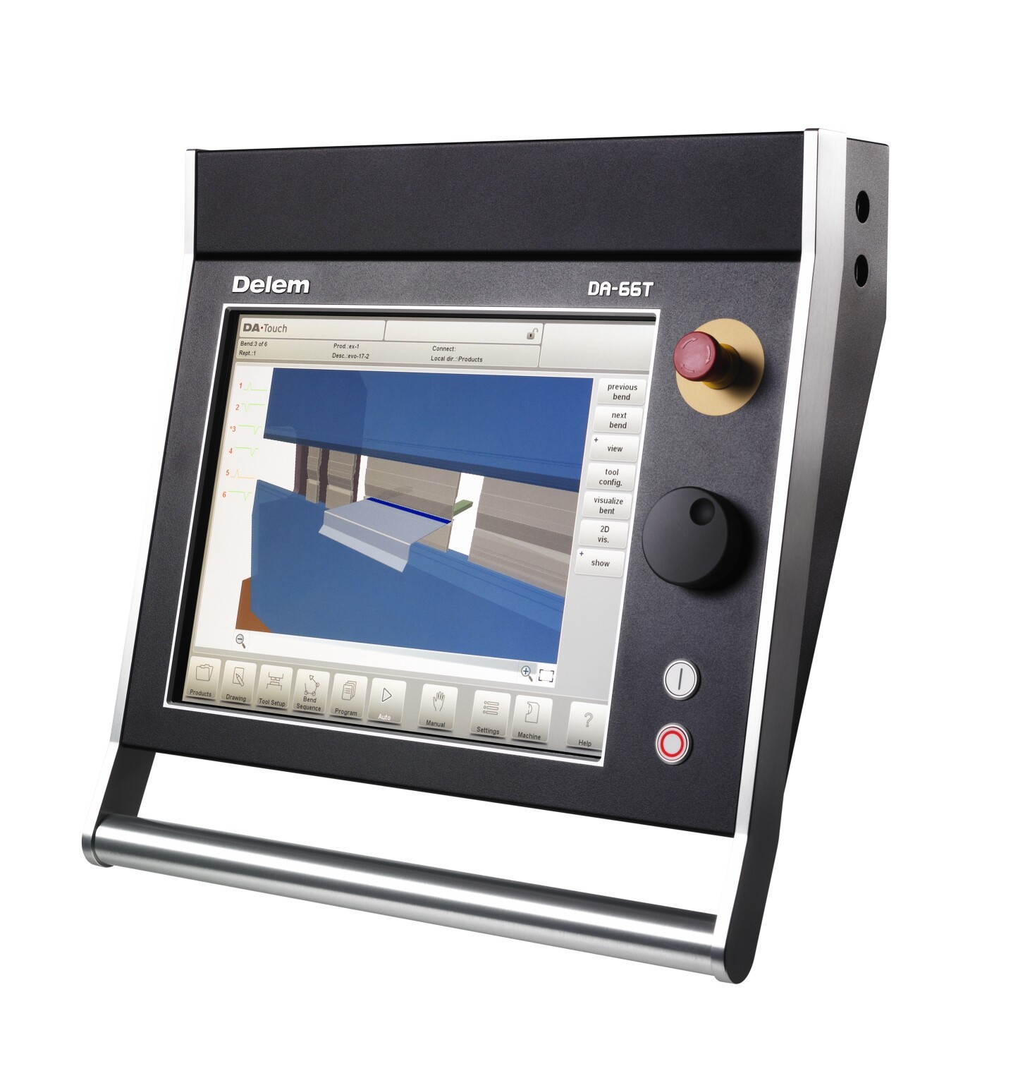
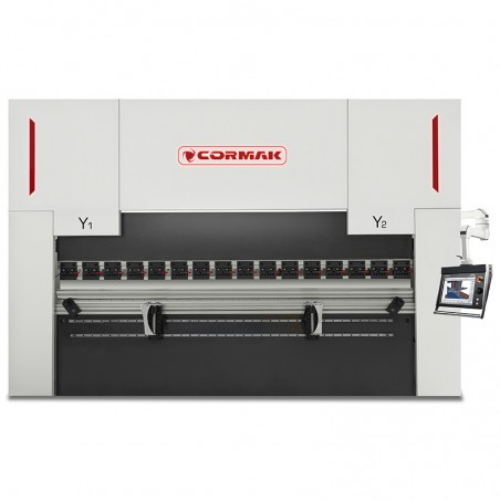
CORMAK press brakes are advanced machines designed for precise sheet metal bending using properly matched punches and dies. Our range includes models equipped with DELEM DA-58T controllers as standard and optionally DELEM DA-53T, DA-66T, DA-69T and CYBELEC 12 controllers, offering a wide variety of functions that allow execution of even the most demanding bending tasks.

| Max. bending thickness (S235) | up to 8.0 mm |
| Nominal pressure | 1600 kN |
| Max. bending length | 3200 mm |
| Throat depth | 320 mm |
| Max. ram stroke | 180 mm |
| Max. opening height | 455 mm |
| Distance between uprights | 2600 mm |
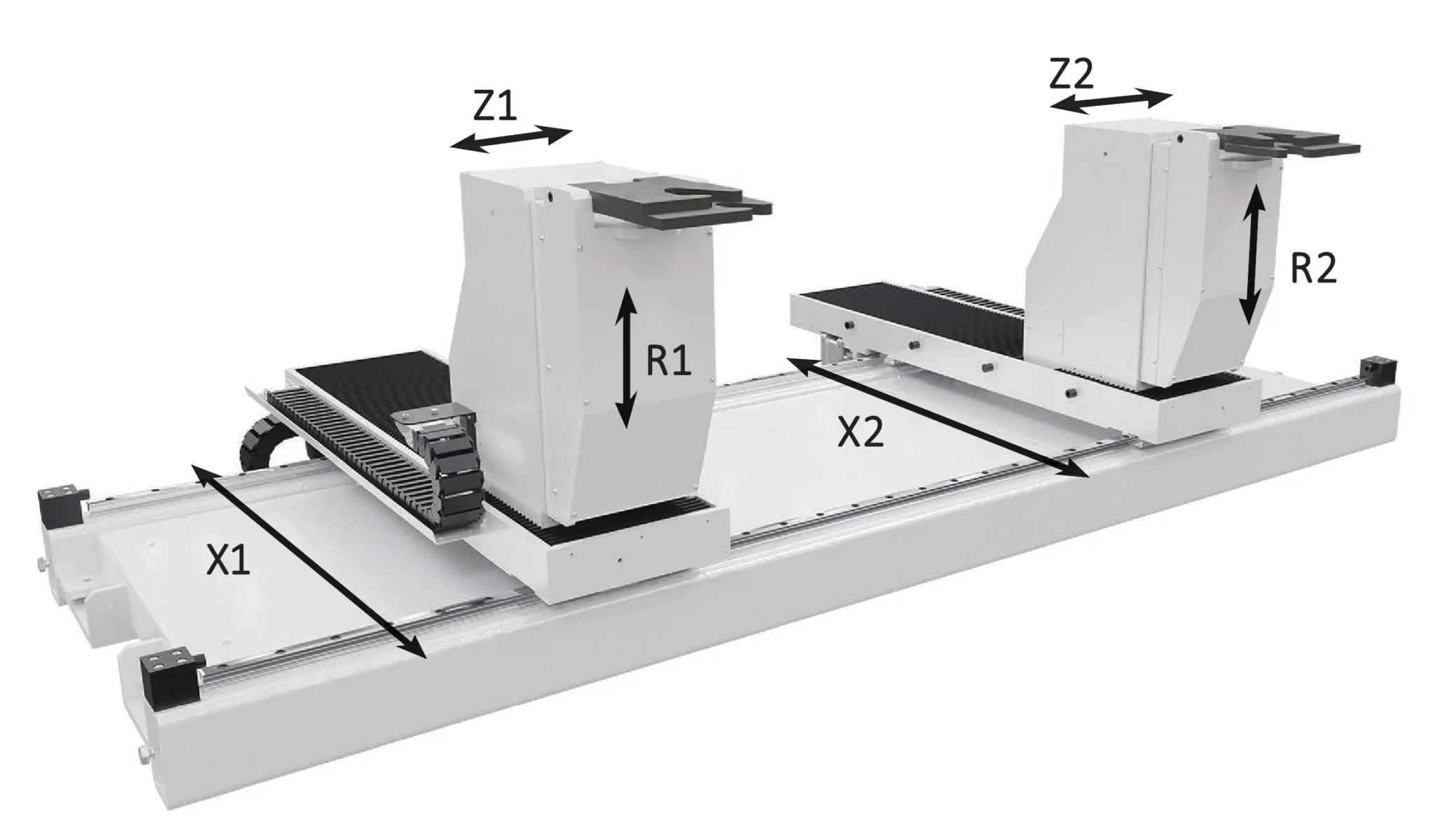
| Backgauge travel | 500 mm |
| Motor power | 11.0 kW |
| Length | 3300 mm |
| Width | 1650 mm |
| Height | 2500 mm |
| Weight | 9500 kg |


Although the entire step bending process may seem complex, CORMAK machines and software are so advanced that they largely automate many operations for the operator.

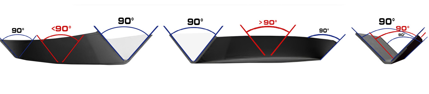
Ensures a consistent bending angle along the entire bending length – (option*)

Ensures a consistent bending angle along the entire bending length – (option*)


Optional DELEM controllers available: DA-53T+2D, DA-66T, DA-69T or CYBELEC 12


The machine combines advanced technology with simplicity of operation, making it an ideal choice both for precise manual tasks and efficient serial production. High-quality components and advanced safety systems ensure reliability and operator protection.
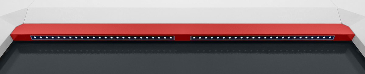
Standard equipment includes a top-class laser safety system that protects the operator and doubles the bending speed.

We never compromise on safety! Premium-quality hydraulic connections and safety valves ensure top reliability.


Beware of pseudo safety systems such as gates or light curtains – they are not CE-compliant and expose employees to serious risks. As an employer, you are responsible for your workers’ safety!


Standard system ensuring stable operating parameters even during long continuous use.
For optimal bending results, it is essential to select the correct tools for the press brake – both die and punch.
CORMAK press brakes continuously measure the bending process and can automatically correct deviations during operation for the best possible outcome.


It is possible to arrange professional training and machine commissioning carried out by a Cormak technician — this service is priced individually.
Contact our advisor to get more information.
*The price quoted is for the machine itself, excluding optional/additional equipment, installation, transport and training— please contact our consultant for more details.
Manufacturer: Cormak

CORMAK JERZY ZALEWSKI
Brzeska 120, 08-110 Siedlce, Poland
phone: +48 501 944 934
export@cormak.pl
phone: +48 609 939 400
export@cormak.pl
phone: +48 609 939 051
export@cormak.pl
phone: +48 609 939 741
export@cormak.pl

Prasa działa bardzo stabilnie. Na razie nie mieliśmy potrzeby serwisowania. Dobrze sprawdza się w codziennej produkcji.
Maszyna działa jak powinna. Jest łatwa w obsłudze, sterowanie jest intuicyjne, a dodatkowe osie zwiększają jej wszechstronność.
Do tej pory nie mieliśmy żadnych problemów z maszyną. Używamy jej do bardziej precyzyjnych zleceń i dobrze się sprawdza.
Prasa jest solidna. Czasami korzystamy z większej liczby osi i sterowanie działa naprawdę dobrze. Polecam!
Prasa działa naprawdę dobrze. Jest dokładna i dobrze wykonana. Używamy jej codziennie w firmie, nie mieliśmy problemów.

Hydraulic Press Brake CORMAK CNC SERVO ELITE 80×3200 DA-58T
CORMAK hydraulic press brakes are advanced machines designed for precise sheet metal bending using well-matched punches and dies. Our range includes models equipped with the DELEM DA-58T controller as standard, with optional DELEM DA53T, DA-66T, DA69T and CYBELEC 12 controllers, offering a wide ...More

Hydraulic Press Brake CORMAK CNC SERVO ELITE 250×2500 DA-58T
CORMAK press brakes are advanced machines enabling precise sheet metal bending thanks to properly selected punches and dies. Our offer includes models equipped as standard with the DELEM DA-58T controller, and optionally with DELEM DA-53T, DA-66T, DA-69T and CYBELEC 12 controllers, providing a wide ...More

Hydraulic Press Brake CORMAK CNC SERVO ELITE 40×1600 DA-58T
CORMAK press brakes are advanced machines designed for precise sheet metal bending with properly selected punches and dies. Our range includes models equipped with the DELEM DA-58T controller as standard, and optionally DELEM DA-53T, DA-66T, DA-69T or CYBELEC 12 controllers, providing a wide ...More

Hydraulic Press Brake CORMAK CNC SERVO ELITE 125×3200 DA-58T
CORMAK press brakes are advanced machines that allow precise sheet bending using properly selected punches and dies. Our range includes models equipped with the standard DELEM DA-58T controller and optional DELEM DA-53T, DA-66T, DA-69T and CYBELEC 12 controllers, providing a wide range of functions ...More

Hydraulic Press Brake CORMAK CNC SERVO ELITE 300×6000 DA-58T
CORMAK press brakes are advanced machines enabling precise sheet metal bending using appropriately selected punches and dies. Our offer includes models equipped as standard with the DELEM DA-58T controller, and optionally with DELEM DA53T, DA-66T, DA69T, and CYBELEC 12 controllers, providing a wide ...More

Hydraulic Press Brake CORMAK CNC SERVO ELITE 200×6000 DA-58T
Press brakes by Cormak are advanced machines designed for precise sheet-metal bending using appropriately selected punches and dies. Our range includes models equipped as standard with DELEM DA-58T controllers and optionally DELEM DA-53T, DA-66T, DA-69T and CYBELEC 12 controllers, offering a wide ...More

Hydraulic Press Brake CORMAK CNC SERVO ELITE 200×3200 DA-58T
CORMAK press brakes are advanced machines designed for precise sheet metal bending using suitably selected punches and dies. Our range includes models equipped as standard with the DELEM DA-58T controller and optionally with DELEM DA-53T, DA-66T, DA-69T or CYBELEC 12 controllers, which provide a ...More

Hydraulic Press Brake CORMAK CNC SERVO ELITE 250×3200 DA-58T
Press brakes by Cormak are advanced machines enabling precise sheet metal bending thanks to properly selected punches and dies. Our range includes models equipped with DELEM DA-58T controllers as standard, and optionally with DELEM DA-53T, DA-66T, DA-69T or CYBELEC 12 controllers, offering a ...More
Hydraulic Press Brake CORMAK CNC SERVO ELITE 300×4000 DA-58T
CORMAK press brakes are advanced machines designed for precise sheet metal bending using carefully selected punches and dies. Our range includes models equipped as standard with the DELEM DA-58T controller and optionally with DELEM DA-53T, DA-66T, DA-69T and CYBELEC 12 , providing a wide array ...More

Hydraulic Press Brake CORMAK CNC SERVO ELITE 250×5000 DA-58T
CORMAK press brakes are advanced machines designed for precise sheet metal bending using properly selected punches and dies. Our range includes models equipped with DELEM DA-58T controllers as standard and optionally DELEM DA53T, DA-66T, DA69T and CYBELEC 12, which provide a wide range of functions for the most demanding bending tasks. ...More

Hydraulic Press Brake CORMAK CNC SERVO ELITE 500×4000 DA-53TX
CORMAK press brakes are advanced machines that enable precise sheet-metal bending thanks to perfectly matched punches and dies. Our range includes models equipped with DELEM DA-53TX controllers as standard and optionally with DELEM DA-53T, DA-58T, DA-66T, DA-69T or CYBELEC 12 controllers, ...More

Hydraulic Press Brake CORMAK CNC SERVO ELITE 63×3200 DA-58T
CORMAK hydraulic press brakes are advanced machines designed for precise sheet metal bending using properly selected punches and dies. Our offer includes models equipped as standard with the DELEM DA-58T controller and optionally with DELEM DA-53T, DA-66T, DA-69T or CYBELEC 12 controllers, ...More

Hydraulic Press Brake CORMAK CNC SERVO ELITE 200×4000 DA-58T
CORMAK press brakes are advanced machines designed for precise sheet metal bending using appropriately selected punches and dies. Our range includes models equipped with DELEM DA-58T controllers as standard and optionally with DELEM DA-53T, DA-66T, DA-69T or CYBELEC 12, offering a wide range of ...More

Hydraulic Press Brake CORMAK CNC SERVO ELITE 300×5000 DA-58T
CORMAK press brakes are advanced machines enabling precise sheet metal bending thanks to perfectly matched punches and dies. The range includes models equipped with the DELEM DA-58T controller as standard and optional controllers DELEM DA-53T, DA-66T, DA-69T and CYBELEC 12, which provide a wide ...More

Hydraulic Press Brake CORMAK CNC SERVO ELITE 500×4000 DA-58T
CORMAK press brakes are advanced machines designed for precise sheet metal bending using appropriately selected punches and dies. Our range includes models equipped with DELEM DA-58T controllers as standard and optionally with DELEM DA53T, DA-66T, DA69T, and CYBELEC 12, offering a wide range of ...More

Hydraulic Press Brake CORMAK CNC SERVO ELITE 40×2000 DA-58T
CORMAK press brakes are advanced machines designed for precise sheet metal bending thanks to perfectly matched punches and dies. Our range includes models equipped with DELEM DA-58T controllers as standard and optionally with DELEM DA-53T, DA-66T, DA-69T or CYBELEC 12 controllers, which ...More
CORMAK press brakes are advanced machines designed for precise sheet metal bending using properly matched punches and dies. Our range includes models equipped with DELEM DA-58T controllers as standard and optionally DELEM DA-53T, DA-66T, DA-69T and CYBELEC 12 controllers, offering a wide variety of functions that allow execution of even the most demanding bending tasks.
2024-02-17
Praca na wysokim poziomie
Zdecydowanie warto. Po kilku miesiącach używania mogę powiedzieć, że działa bezproblemowo, z łatwym sterowaniem.