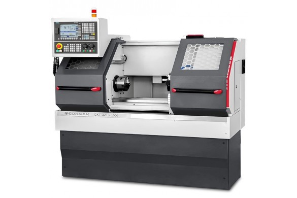
Continuous Spindle-Speed Control in CNC Lathes – How to Select Cutting Parameters
Continuous Spindle-Speed Control in CNC Lathes – How to Select Cutting Parameters
Continuous spindle-speed control makes it possible to match a CNC lathe to the workpiece material, current diameter, tool type and machining operation. It directly affects surface quality, insert life, process stability and safe operation.
There is no single correct rpm for every job. Parameters must be selected from cutting speed, current diameter, material grade, insert geometry and grade, feed, depth of cut, coolant, machine power and the rigidity of the entire setup.
What Is Continuous Spindle-Speed Control?
Continuous spindle-speed control lets the operator set rpm across a wide range rather than relying on a limited number of fixed gearbox speeds. On a CNC lathe, rpm may be commanded through the program, machine control or CAM output.
It is especially useful when a workshop machines different diameters and materials. It allows suitable conditions for roughing, finishing, grooving, threading and facing.
Spindle rpm range alone does not define the lathe’s capability. Available torque, spindle power, maximum rpm, machine–chuck–workpiece–tool rigidity and the limits stated by the machine and chuck manufacturers are also critical.
Why Does Spindle Speed Matter?
Spindle speed is derived from cutting speed. Excessive rpm can accelerate tool wear, raise temperature and increase the risk of chatter. Too little rpm can reduce productivity, impair chip control or worsen surface finish. It must always be considered together with feed and depth of cut.
Correctly selected conditions can support:
- more stable cutting;
- more repeatable surface quality;
- more predictable insert or tool wear;
- better dimensional control;
- lower risk of vibration, built-up edge and tool damage.
Adjust speed when material, diameter, tool overhang, workholding, coolant, operation type or cutting-edge condition changes. Toolmaker data provides the starting point; final values should be proven on the actual machine and application.
How to Calculate Spindle Speed
Use the following relation to estimate spindle speed:
n = (1000 × Vc) / (π × D)
A common workshop approximation is:
n = 318 × Vc / D
- n – spindle speed in rpm;
- Vc – cutting speed in m/min;
- D – current cutting diameter in mm;
- 318 – rounded value of 1000/π.
Steel example
For steel with a 50 mm diameter at an indicative cutting speed of 120 m/min:
n = 318 × 120 / 50 = 763 rpm
A suitable starting value is about 760 rpm, then verify the result by reviewing surface finish, chip form, process sound, spindle load and insert condition.
The formula does not include every technological condition. Recommended cutting speed depends on material grade and hardness, interrupted cuts, insert geometry, coolant and required tool life.
Constant Surface Speed in CNC: G96 and RPM Limiting
In CNC turning, the spindle can run at fixed rpm or constant surface speed. On many controls, constant surface speed is commanded with G96, while fixed rpm uses G97. Exact syntax depends on the controller, so always follow the machine documentation.
With constant surface speed, rpm automatically increases as the workpiece diameter becomes smaller. This is useful for facing and profiling because it supports more consistent cutting conditions across a changing diameter.
A maximum rpm limit is essential. Near the workpiece centreline, diameter approaches zero and calculated rpm rises rapidly. The program must set a safe maximum that respects the lathe, chuck, workholding and workpiece balance. Never exceed the limits specified by the machine or chuck manufacturer.
Constant surface speed is not always the right choice. With unbalanced parts, workholding limitations, some threading operations or processes governed by specific instructions, fixed rpm may be safer or technically necessary.
Parameters for Steel, Aluminium and Stainless Steel
The values below are indicative starting ranges for external turning under stable conditions. They do not replace the data for a specific insert, HSS tool or workpiece grade. Use more conservative settings for interrupted cuts, long overhang, weak workholding or limited machine power.
Steel
| Tool | Indicative Vc | Notes |
|---|---|---|
| HSS tool | 20–40 m/min | Depends on steel grade, coolant and edge geometry. |
| Carbide insert | 80–180 m/min | Typical starting band for stable turning. |
| Coated steel insert | 120–250 m/min | Select according to ISO P grade, roughing or finishing, and toolmaker data. |
Where temperature, wear or chatter becomes excessive, check workholding, feed, depth of cut, overhang and coolant in addition to Vc.
Aluminium
| Tool | Indicative Vc | Notes |
|---|---|---|
| HSS tool | 60–120 m/min | Use a sharp edge and monitor built-up edge. |
| Carbide insert | 200–500 m/min | Depends on alloy, machine and coolant. |
| Polished aluminium insert | 300–800 m/min | Higher Vc is possible only where supported by toolmaker and machine limits. |
For aluminium at 40 mm diameter and Vc = 300 m/min, spindle speed is about 2385 rpm. Check maximum rpm limits for the lathe, chuck and workholding before applying it.
Stainless steel
| Tool | Indicative Vc | Notes |
|---|---|---|
| HSS tool | 10–25 m/min | Lower speeds and closer monitoring of temperature and edge condition. |
| Carbide insert | 50–120 m/min | Depends on stainless grade and setup rigidity. |
| Stainless-steel insert | 80–180 m/min | Follow the toolmaker’s cooling and cutting-data guidance. |
Avoid rubbing when turning stainless steel. Feed must provide true cutting rather than allowing the edge to slide over the surface, which can promote work hardening and faster wear.
Feed and Depth of Cut – Set Them Together with RPM
Cutting speed is only one part of the setup. Turning also uses feed per revolution f, usually in mm/rev, and depth of cut ap, in mm.
Feed rate can be calculated as:
vf = n × f
- vf – feed rate in mm/min;
- n – spindle speed in rpm;
- f – feed per revolution in mm/rev.
Finishing commonly uses lower feed to support surface finish. Roughing may use higher feed and ap when machine power, setup rigidity, insert selection and chip control permit it.
Do not reduce feed indefinitely to improve surface finish. Too little feed relative to the cutting-edge geometry can create rubbing, poor chip control and excess heat. Select feed from toolmaker data, insert nose radius and required surface finish.
Example Spindle-Speed Table
The table uses n = 318 × Vc / D. It gives indicative rpm for the stated cutting-speed examples, not universal settings for every tool or material grade.
| Material | Cutting speed | Ø 20 mm | Ø 50 mm | Ø 100 mm |
|---|---|---|---|---|
| Steel | 120 m/min | 1908 rpm | 763 rpm | 382 rpm |
| Aluminium | 300 m/min | 4770 rpm | 1908 rpm | 954 rpm |
| Stainless steel | 80 m/min | 1272 rpm | 509 rpm | 254 rpm |
At high rpm, always consider the maximum permissible speed for the chuck, jaws, fixtures and workpiece. Before starting, confirm correct clamping and suitable balance within the capabilities of the station.
Common Selection Mistakes
- using the same rpm for steel, aluminium and stainless steel;
- calculating rpm from nominal rather than current cutting diameter;
- not setting a maximum spindle-speed limit in constant-surface-speed mode;
- ignoring limits of the chuck, jaws and workholding;
- using excessive Vc with unstable workholding or long tool overhang;
- using feed so low that rubbing replaces stable cutting;
- running a worn insert or a tool with built-up edge;
- using insufficient coolant or chip evacuation where the operation requires it.
A Practical Parameter-Setting Workflow
- Identify material and condition. Determine grade, hardness, scale, interrupted cutting and surface condition.
- Select the tool. Check insert, chipbreaker geometry, grade, nose radius and manufacturer cutting data.
- Determine current diameter D. This is the basis of rpm calculation.
- Choose a starting Vc. Use a conservative value from the toolmaker’s recommended range.
- Calculate rpm and set limits. In G96 mode, set a safe maximum spindle speed.
- Select feed and ap. Consider required finish, rigidity, power and chip control.
- Run a trial and observe. Review chip, surface, vibration, spindle load and edge condition.
- Change one variable at a time. This makes the source of a problem easier to identify and preserves repeatability.
FAQ
What does continuous spindle-speed control mean?
It means rpm can be set precisely across a wide range. In CNC, speed may be program-controlled and, under constant surface speed, may change with the workpiece diameter.
Do higher rpm always improve surface finish?
No. Surface quality also depends on feed, nose radius, insert geometry, edge condition, workholding, material and vibration. Excess rpm can worsen tool conditions.
Should stainless steel always be machined at low rpm?
Stainless cutting speed is often lower than aluminium, but the correct value depends on stainless grade, insert, coolant and rigidity. Follow the toolmaker’s data.
How should lathe motor power be selected?
Power should be chosen for planned operations, maximum diameter, depth of cut, feeds, materials and output requirements. Power alone does not replace rigidity, spindle torque or correct workholding.
Summary
Continuous spindle-speed control in CNC lathes helps match cutting conditions to current diameter, material and tool. The basic calculation remains n = 318 × Vc / D, but the result must always be checked against the limits of the lathe, chuck and workholding.
Best results come from selecting Vc, rpm, feed, depth of cut and coolant together. In CNC, particular attention should be paid to constant surface speed and a safe maximum spindle-speed limit.
Latest blog postsAll articles →