

The basket is empty.


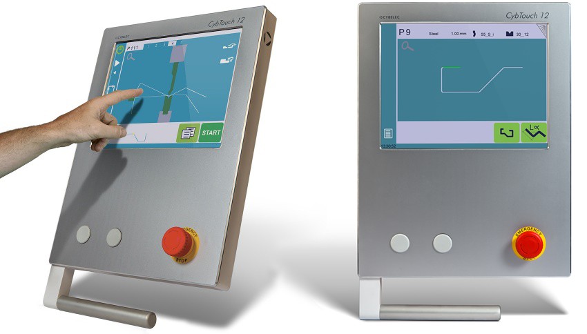
The ULTIMATE series CNC press brake is a modern machine for bending sheet metal at any angle. The design with increased efficiency allows for maintaining precise bending during longer work. As standard, the press has four axes: X, Y1, Y2, R and an automatic deflection arrow. CNC Cybelec 12PS control, pressure from 60 to 400 tons and bending length from 1300 to 6100 mm.

Ultimate press brakes are an advanced tool used in the industry for edging and bending materials. They are a versatile machine that allows precise and efficient finishing of edges on a variety of materials, such as steel, aluminum and plastics.
Ultimate press brakes are designed with efficiency and reliability in mind. They feature a solid construction that ensures stability during operation. The machines also feature advanced control systems that allow programming of various operating parameters, such as edging speed, bending angle and press force.
One of the main advantages of the Ultimate press brakes is their ease of use. The intuitive user interface allows the operator to easily program and control the machining process. Additionally, the presses are equipped with advanced safety systems that ensure safe use. Thanks to their high performance, the EASY press brakes are the ideal solution for manufacturers who require fast and precise edge processing. It can be used in various industries, such as the metal industry, carpentry, furniture production and the plastics industry.
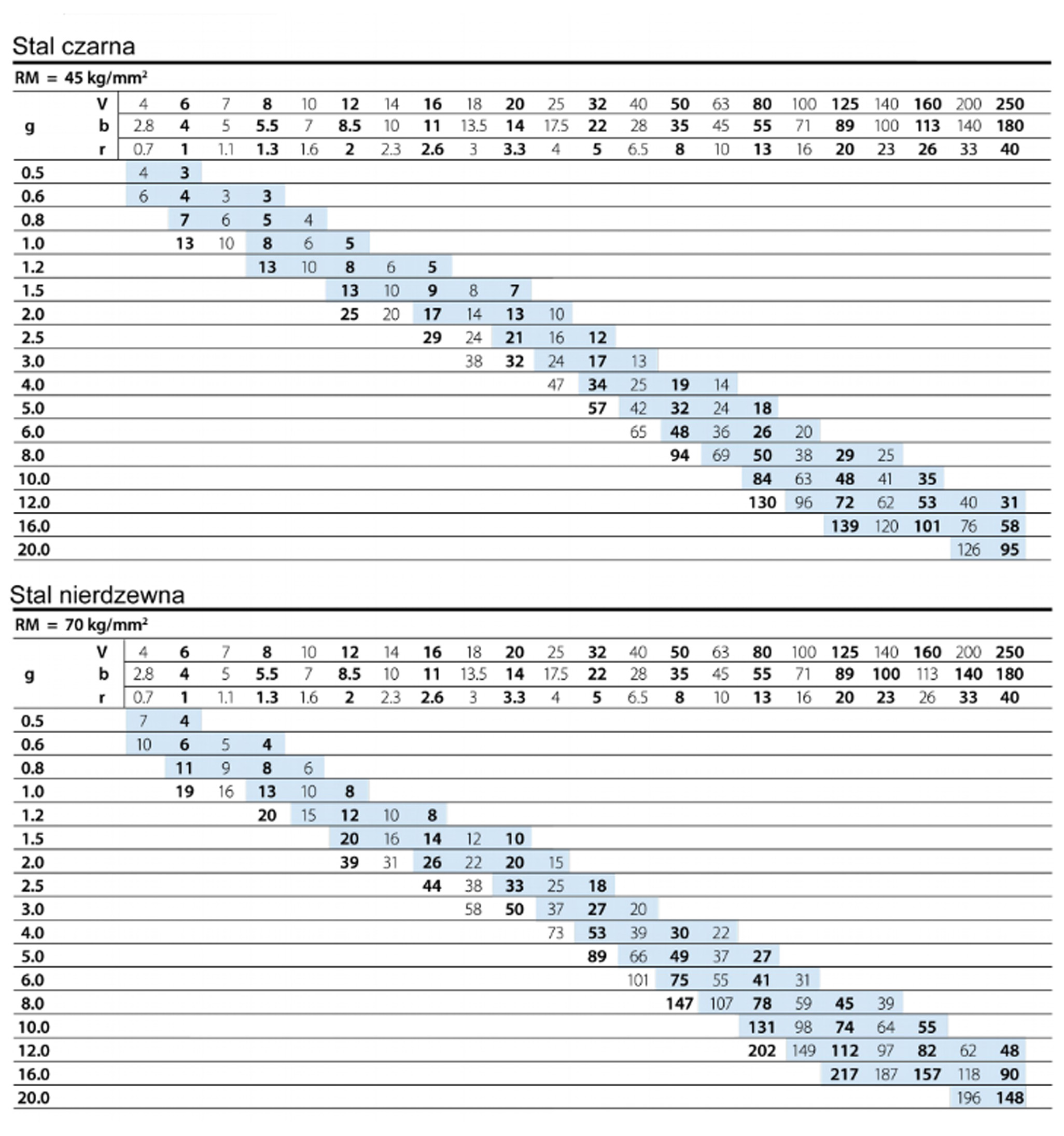
| Max. thickness of bent sheet metal (S235) | up to 6.0mm |
| Nominal pressure | 1250kN |
| Maximum length of bent sheet metal | 3100mm |
| Depth of cut in beams (throat) | 320mm |
| Maximum stroke of the moving beam | 120mm |
| Maximum opening height | 390mm |
| Distance between beams | 2700mm |
| Rear bumper departure | 600mm |
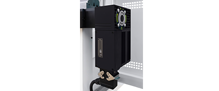
| SERVO engine power | 11.0kW |
| Length | 3870mm |
| Width | 1550mm |
| Height | 2400mm |
| Weight | 7500 kg |
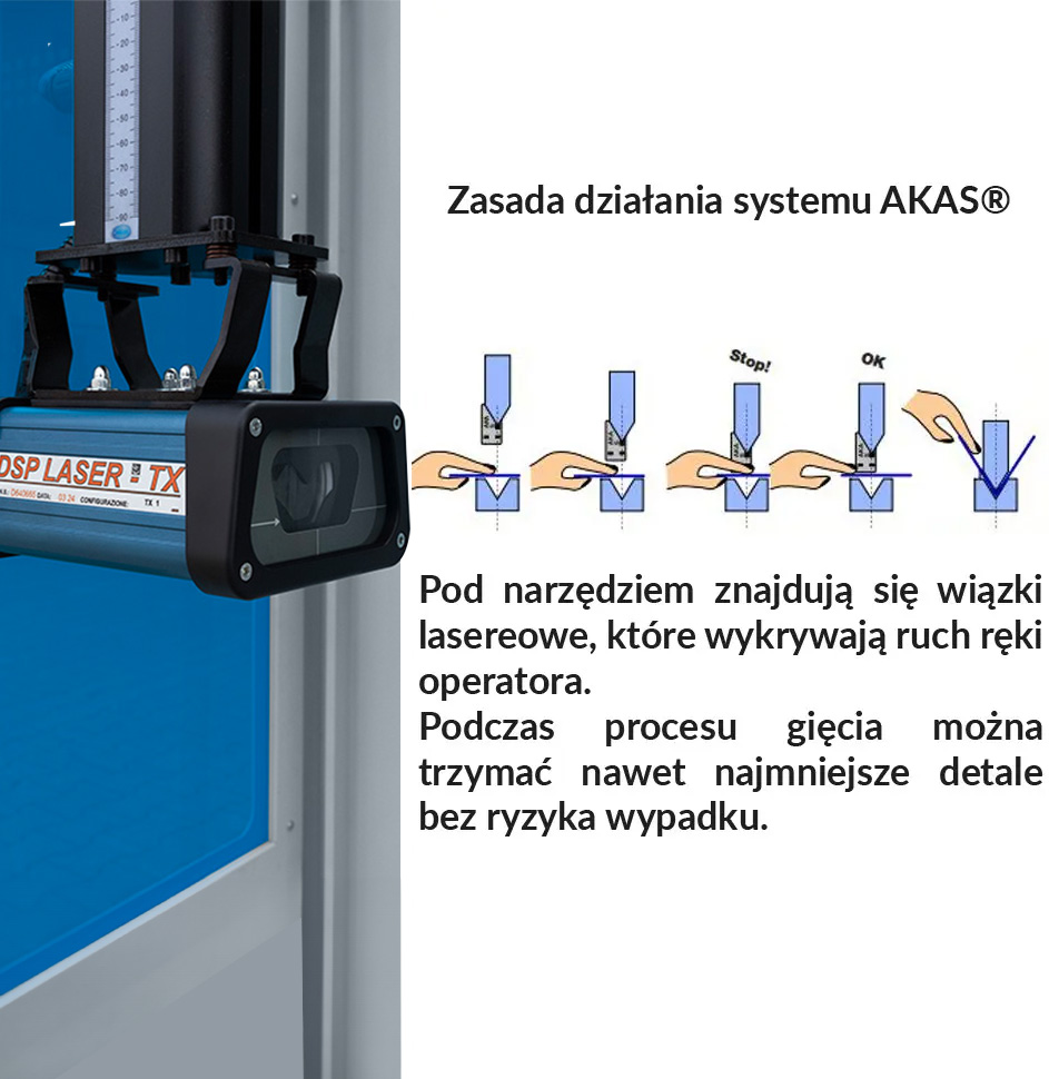
Ensures the same bending angle is maintained along the entire bending length
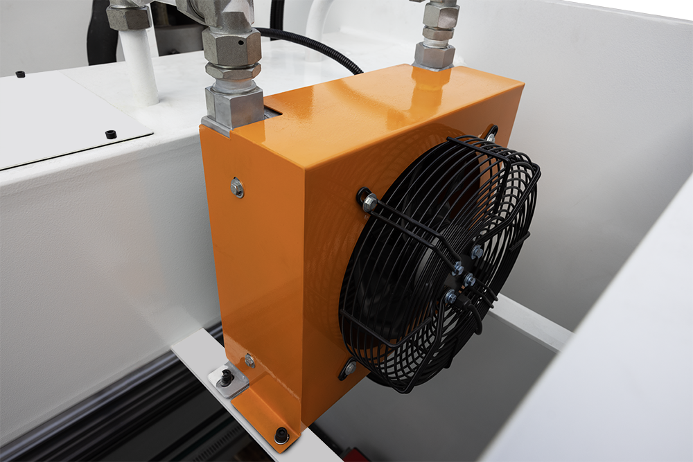
The SOil Cooling System guarantees the stability of the machine's operating parameters even after long, continuous use.


Axes Y1, Y2 - these are the axes responsible for the work of the bending beam. Y1 is the left side and Y2 is the right side. The entire bending process is controlled by the CNC system using a hydraulic system integrated with the measuring system, which consists of measuring rulers located on the left and right side of the machine. CNC-controlled press brakes are synchronous machines, i.e. those that have independent control of the left and right actuator, which allows us to freely correct parallelism and correct the bending angle independently on both sides Y1 and Y2.
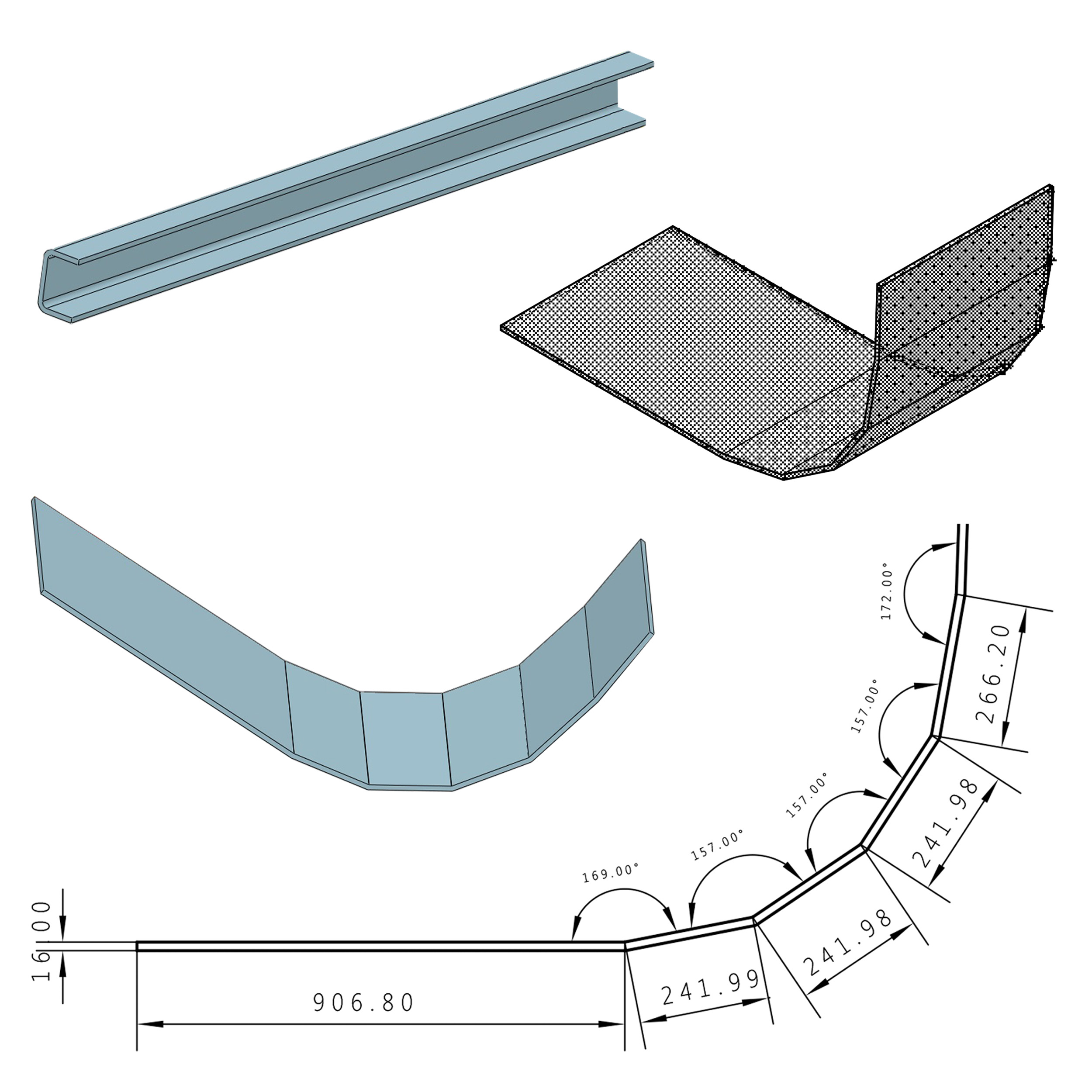
X - is the axis responsible for the movement of the bumper in the front-back plane. It is responsible for maintaining the dimension of the bent sides of the detail. It is driven by a stepper motor or servo drive, while the executive mechanism transmitting the drive is ball screws. The encoder is responsible for determining the position and accuracy of the bumper. CNC controls can automatically calculate the X position in order to obtain the appropriate bending dimension, taking into account the thickness, type of material, tools used, bending angle and whether the dimension in the drawing is external or internal.
R - is also the machine's bumper axis, responsible for movement in the up-down plane. It is most often driven by a servo-controlled gear. The encoder is also responsible for position and accuracy. The zero point for the R axis is the height of the currently mounted matrix on the press table. In modern CNC controls, the bumper fingers have several reference planes or sheet metal support, after selecting the bumper position in the control, the machine will automatically correct the R height and the X position of the bumper.
 The body of the press brake is made of side walls and a table. The pressure on the table is exerted by the bending beam moving in the body guides. Both the table and the beam are supported at two points. When very large forces are applied to the bent sheet metal, the table deflects. This causes a problem with obtaining the set angle in the middle of the table. In order to obtain the same angle along the entire length of the bent sheet metal, it is necessary to equip the machine with a table compensation system. However, the most commonly used system is a mechanical system. This is the so-called opposite wave system. The press table is milled from the bottom so that two strips with opposite waves fit in it. The lower strip is fixed, while the upper one is moved manually using a crank with a built-in scale or automatically by a servo-driven gear. This system perfectly compensates for the table deformations that arise in the process of bending the sheet metal, while ensuring high accuracy in maintaining the value of the set angle.
Manufacturer: Cormak

CORMAK JERZY ZALEWSKI
street Brzeska 120, 08-110 Siedlce, Poland
phone: +48 501 944 934
export@cormak.pl
phone: +48 609 939 400
export@cormak.pl
phone: +48 609 939 051
export@cormak.pl
phone: +48 609 939 741
export@cormak.pl

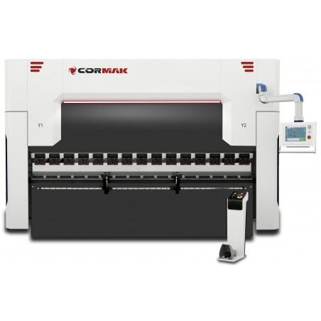
ULTIMATE HYDRAULIC EDGE PRESS 130x3100 Cybelec 4+1 AXLE
The ULTIMATE series CNC press brake is a modern machine for bending sheet metal at any angle. The design with increased efficiency allows for maintaining precise bending during longer work. As standard, the press has four axes: X, Y1, Y2, R and an automatic deflection arrow. CNC Cybelec 12PS ...More
The ULTIMATE series CNC press brake is a modern machine for bending sheet metal at any angle. The design with increased efficiency allows for maintaining precise bending during longer work. As standard, the press has four axes: X, Y1, Y2, R and an automatic deflection arrow. CNC Cybelec 12PS control, pressure from 60 to 400 tons and bending length from 1300 to 6100 mm.